photos:PowerOne PSU, round two
SGI PowerOne PSU, round two
See also my previous adventures.
Fault symptoms:
When power is applied to the PSU, an oscillation happens and the +5, +12, -12 and -5VDC outputs
switch on/off rapidly. As soon as the PSU is switched on, voltages are good.
When the PSU is switched off, the output modules actually switch off.
Observations: The System Power Bus carries +300VDC with little ripple. As soon as the PSU is powered up properly, it is capable of supplying enough power to run a 4D/440VGX, taking ~ 900W from the mains. It is therefore assumed that the problem is not in the EMI filter, rectifier or big capacitators.
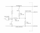
The SGI Custom PCB has very few components, but if the O/T signal goes high it will raise the Inhibit signal. It has been verified that this doesn't happen.
Relevant links:
- High Power Modular Products Data Sheet
- Application Note: DESCRIPTION OF SIGNALS (PF, INHIBIT, AND O/T) LOCATED ON THE 12-PIN CONNECTOR
- Application Note: Mechanical Drawings
 |
||
 |
||
 |
||
 |
||
Date: 2009:11:18 21:11:37
Date: 2009:11:18 21:56:50
Date: 2009:11:18 21:40:02
Date: 2009:11:18 21:55:38
 |
||
Date: 2009:11:18 21:46:36
Date: 2009:11:18 21:57:27
Date: 2009:11:18 21:57:57
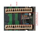
with functional sections
 |
||
 |
||
 |
||
for one module
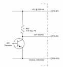
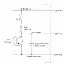
| pin | function |
|---|---|
| 5 | PF signal |
| 6 | O/T signal |
| 7 | VCC (+5V @ 100mA) |
| 10 | GND |
| 11 | Inhibit |
The 'inhibit' signal is active high and pulled up to VCC internally. If you pull down the inhibit signal the PSU starts up. In an SGI 4D system, the power switch on the front panel shorts the inhibit signal (pin 11) to GND (pin 10).
The Custom PCB (BD60246A / ASSY60247) contains:
- A 1kOhm resistor to limit the current when shorting the inhibit signal to ground.
- A simple circuit to pull up the inhibit signal when O/T goes high.
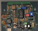
Functional sections identified on the backplane (BD57063A / ASSY57065):
- Inbetween the 'slots' are the rectifier/filter & sync circuits for the DC output modules.
- The two fat vertical PCB traces are the 300VDC distribution, to the left GND, right is 300VDC. It is 'hot' as soon as the power cord is connected, even when 'inhibit' is high!
- Above the white opto-coupler is the system control section, with it's own 5VDC supply (an 7805), an overtempterature protection built around an Airpax 6600 and power fail detection.
- Below the white opto-coupler is a yet-to-be-investigated circuit, this is most likely the bias supply inverter, and the rectifier/filter and fan control.